For the Cantilever Beam and Loading Shown
When you get to a load add to the Shear Force Diagram by the amount of the force. The support reactions as indicated in the free-body diagram are A y A x and M.
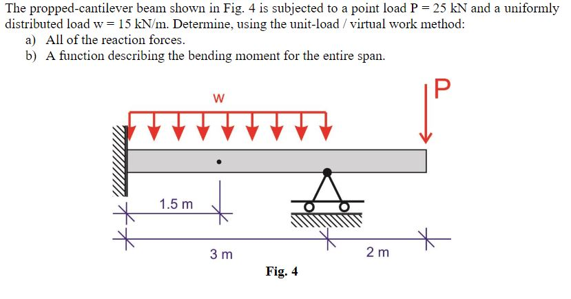
Solved The Propped Cantilever Beam Shown In Fig 4 Is Chegg Com
Beam equations for Resultant Forces Shear Forces Bending Moments and Deflection can be found for each beam case shown.

. The fixed beam features two fixed supports one at each end. The bending moment acting on a section of the beam due to an applied transverse force is given by the product of the applied force and its distance from that. This step is based on a simple shear force formula sum of vertical forces which is.
But we cant put a real bridge on kitchen scales and sometimes the loading is a bit more complicated. In other words the fixed beam offers redundancy in terms of. Determine the reactions at support A.
A cantilever beam is subjected to a uniformly distributed load and an inclined concentrated load as shown in figure 39a. The free-body diagram of the entire beam is shown in Figure 39b. Handy calculators have been.
For a plane structure lying in the xy plane and subjected to a. Bending moments are produced by transverse loads applied to beams. Simply select the picture which most resembles the beam configuration and loading condition you are interested in for a detailed summary of all the structural properties.
If both ends are fixed in this way the reactions are not statically determinate. Find the height h if the maximum deflection is not to. 10kN 20kN -10kN.
The cantilever beam shown in Fig. In practice it is not usually possible to obtain perfect fixing and the fixing moment applied will be related to the angular movement of the support. The fixed beam features more supports than required to be statically sound.
In this example imagine a beam 12m long with a 60kg load 6m from one end and a 40kg load 9m. E48 has a rectangular cross-section 50 mm wide by h mm high. The simplest case is the cantilever beam widely encountered in balconies aircraft wings diving boards etc.
Indeed the second fixed support could be removed entirely turning the structure to a cantilever beam which is still a sound load bearing structure. 9 Equations of Static Equilibrium A structure is considered to be in equilibrium if initially at rest it remains at rest when subjected to a system of forces and couples. A beam which is fixed at one end in this way is called a Cantilever.
If a structure is in equili-brium then all its members and parts are also in equilibrium. Floor Beam beam 1 to Girder beam 2 Conditions Coped Beam. Beam Design Formulas.
In this case we have come to a negative 20kN force so we will minus 20kN from the existing 10kN. When in doubt about the rigidity it is safer to assume that the beam is freely. Being able to calculate the forces acting on a beam by using moments helps us work out reactions at supports when beams or bridges have several loads acting upon them.
Note cables attached to wall and strung to a. Bending moments and beam curvatures. Keep moving across the beam stopping at every load that acts on the beam.
Increases loading of walls with clayey backfill sketched at upper left Walls backfilled with free draining materials will tend to fare much better Titling cantilever wall in Grand Rapids Michigan A tilt of 10o increases the load by 20 This problem likely exacerbated by undercutting of the footing by the Grand River at left.
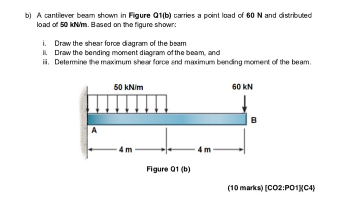
Solved B A Cantilever Beam Shown In Figure Q1 B Carries A Chegg Com
Solved For The Cantilever Beam And Loading Shown Determine Chegg Com

Check My Work For The Cantilever Beam And Loading Shown Determine The Slope And Deflection At Homeworklib

What Is The Standard Size Of A Cantilever Beam Balcony And Its Slab With Width 6 Length 10 Quora Slab Steel Structure Buildings Image House

Pin By Am Makrani On 25 Feet Civil Engineering Design Engineering Design Image House

The Cantilever Beam Shown In Fig P10 40 Consists Of A W8 31 Structural Steel Wide Flange Shape E 29 000 Ksi I 110 In 4 For The Loading Shown Use Discontinuity

Draw The Shear Diagram For Cantilever Beam Bending Moment Beams Diagram
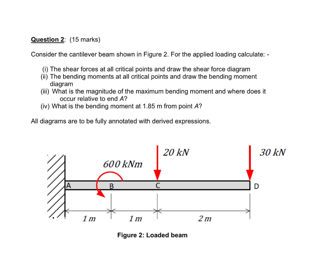
Solved Question 2 15 Marks Consider The Cantilever Beam Chegg Com

Shear Force And Bending Moment Diagram For Cantilever Beam Civil Snapshot Bending Moment Shear Force Beams

The Cantilever Beam Shown In Fig P10 58 Consists Of A Rectangular Structural Steel Tube Shape E 200 Gpa I 400 10 6 Mm 4 For The Loading Shown Determine A The

The Cantilever Beam Shown In Fig P10 58 Consists Of A Rectangular Structural Steel Tube Shape E 200 Gpa I 400 10 6 Mm 4 For The Loading Shown Determine A The

Different Types Of Beams In Civil Engineering Civil Engineering Beams Civil Engineering Construction

Superposition Beam Deflection Table Beams Civil Engineering Design Flex Banner Design
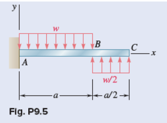
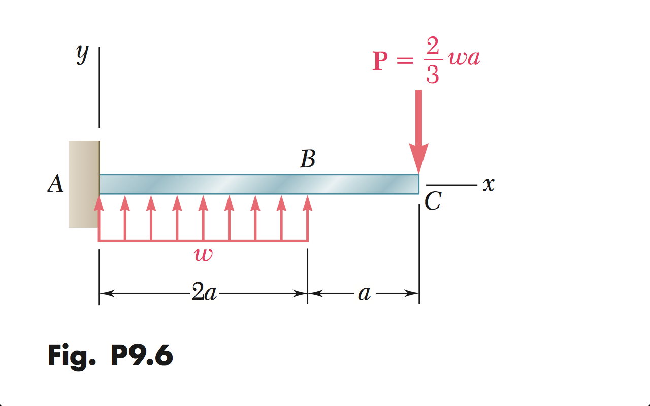
Solved Problem 9 5 For The Cantilever Beam And Loading Chegg Com
2
Pin On Structuraldetails Store Catalogue
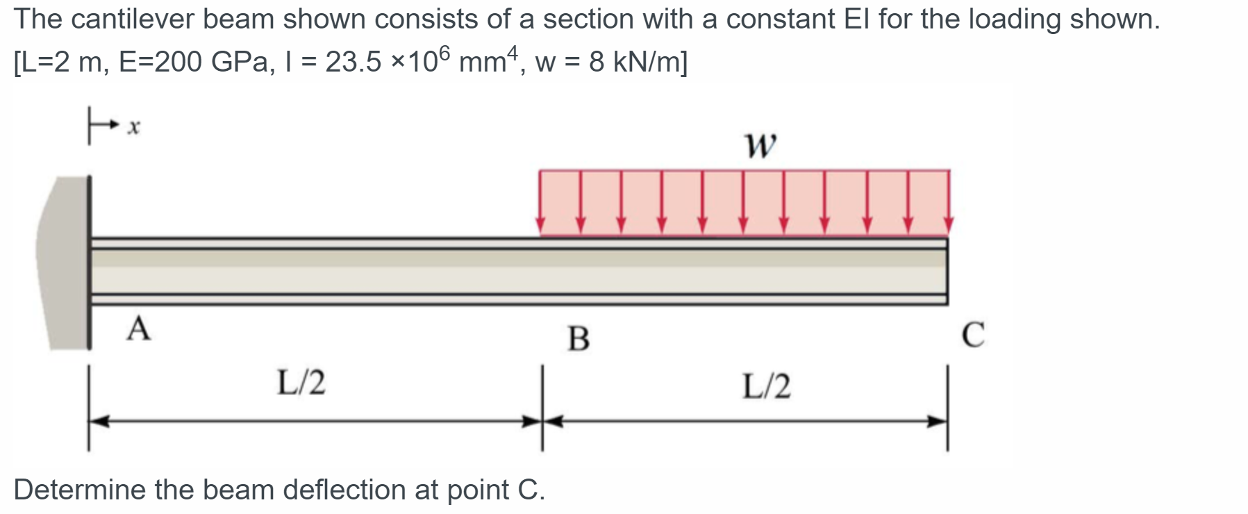
Solved The Cantilever Beam Shown Consists Of A Section With Chegg Com

Q5 The Cantilever Beam Ac Is Subjected To The Load Case Shown In Figure 5 For The Loading Shown Do The Following 10 Marks A Calculate The Magnitude And Direction Of The

Solution To Problem 437 Relationship Between Load Shear And Moment Strength Of Materials Review At Mathalino


Comments
Post a Comment